10月2日

10月2日

$28.07
  • Description:PWR XFMR LAMINATED 20VA CHAS MT
  • Series:-
  • Mfr:Signal Transformer
  • Package:Box

SKU:dd29a3707ab2 Category: Brand:

  
  • Quantity
    • -
    • +
  •    
ChipApex WhatsApp

Consult the customer manager about the wholesale price.

consultation hotline:86-132-6715-2157

email:chipapexlimited@gmail.com
Contact the product manager for consultation. One-stop consultation is available.


Do you want a lower wholesale price? Please send us your inquiry and we will reply immediately.

*
*
*
*
Submitting!
Submission successful!
Submission failed!
Email error!
Phone number error!

Product Detailed Parameters

  • Description:PWR XFMR LAMINATED 20VA CHAS MT
  • Series:-
  • Mfr:Signal Transformer
  • Package:Box
  • Type:Laminated Core
  • Voltage - Primary:105V, 115V, 125V
  • Voltage - Secondary (Full Load):Parallel 5V, Series 10V
  • Current - Output (Max):Parallel 4A, Series 2A
  • Primary Winding(s):Single, Multiple Taps
  • Secondary Winding(s):Single, Multiple Taps
  • Center Tap:Yes
  • Power - Max:20VA
  • Mounting Type:Chassis Mount
  • Termination Style:Solder, Quick Connect
  • Size / Dimension:79.40mm L x 53.90mm W
  • Height - Seated (Max):69.90mm
  • Voltage - Isolation:1500Vrms
  • Weight:1.5 lbs (680.4 g)

Download product information

10月2日

Buying Guide
Summary

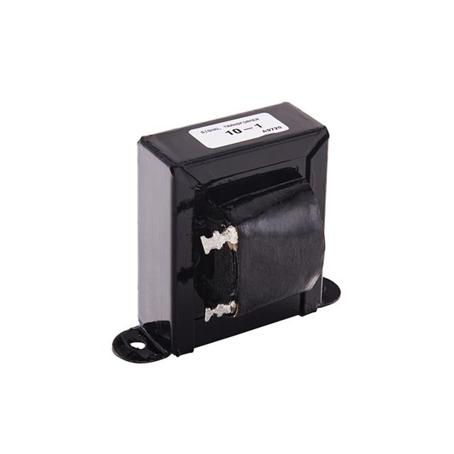
Signal Transformer 10%E6%9C%882%E6%97%A5 is selected in Power Transformers category when protection behavior and transient response must be validated under realistic load steps. Key specs include Description (PWR XFMR LAMINATED 20VA CHAS MT), Mounting (Chassis Mount), and Packaging (Box).

Selection Notes
  • For 10%E6%9C%882%E6%97%A5, check Primary Winding(s) (Single, Multiple Taps) against the datasheet conditions and your system-level constraints.
  • Verify the mounting type (Chassis Mount) fits your manufacturing and inspection workflow.
  • Confirm the supply current (Parallel 4A, Series 2A) is acceptable for standby and active operation.
  • Check Weight (1.5 lbs (680.4 g)) against the datasheet conditions and your system-level constraints.
Alternates & Substitutions
  • In Power Transformers designs, define acceptance criteria up front so alternates can be qualified and repeated in production.
  • If substitutions are likely, write down the non-negotiables and re-check them when the supply chain changes, not after field failures.
  • For substitutions, match the footprint-related items first: mounting Chassis Mount, packaging Box.
  • For power parts, match input/output limits first, then validate stability, protection behavior, and thermals under load steps and transients.
FAQ

Which Voltage - Isolation is specified for 10%E6%9C%882%E6%97%A5?
1500Vrms

How is 10%E6%9C%882%E6%97%A5 mounted?
Chassis Mount

What Voltage - Primary does 10%E6%9C%882%E6%97%A5 have?
105V, 115V, 125V

What is the Height - Seated (Max) of 10%E6%9C%882%E6%97%A5?
69.90mm

Application Scenarios

In practice, the question for Signal Transformer 10%E6%9C%882%E6%97%A5 in Power Transformers is whether it stays inside the electrical/thermal envelope while remaining easy to validate and support. A disciplined power selection improves robustness by reducing sensitivity to layout parasitics and component tolerance. In practice, when power margins are designed in, downstream signal integrity and timing margins are usually easier to hold in production. Across medical devices, power integrity and fault response are validated as part of safety and reliability requirements. Within instrumentation, clean rails reduce measurement noise so converter and analog front-end accuracy is not limited by supply ripple. In robotics platforms, sudden actuator and compute load steps stress converters, so transient response and protection behavior are validated together.

Compatibility Advice
  • To avoid late surprises, check self-heating and thermal coupling on the PCB so performance does not shift after heat soak. This helps field behavior stay predictable across lots.
Project Fit
  • Ideal when you can measure and verify Signal Transformer 10%E6%9C%882%E6%97%A5 for Power Transformers integration in the final enclosure, when you can validate derating, self-heating, and frequency behavior on the assembled system.
  • Not ideal when integrating Signal Transformer 10%E6%9C%882%E6%97%A5 for Power Transformers, derating and self-heating cannot be verified, so performance drift may appear after deployment, because the behavior cannot be verified in a repeatable way.
10月2日10月2日
$28.07
Buy Now