10月6日

10月6日

$70.22
  • Description:PWR XFMR LAMINATED 60VA CHAS MT
  • Series:-
  • Mfr:Signal Transformer
  • Package:Box

SKU:ce5aedffa8a6 Category: Brand:

  
  • Quantity
    • -
    • +
  •    
ChipApex WhatsApp

Consult the customer manager about the wholesale price.

consultation hotline:86-132-6715-2157

email:chipapexlimited@gmail.com
Contact the product manager for consultation. One-stop consultation is available.


Do you want a lower wholesale price? Please send us your inquiry and we will reply immediately.

*
*
*
*
Submitting!
Submission successful!
Submission failed!
Email error!
Phone number error!

Product Detailed Parameters

  • Description:PWR XFMR LAMINATED 60VA CHAS MT
  • Series:-
  • Mfr:Signal Transformer
  • Package:Box
  • Type:Laminated Core
  • Voltage - Primary:105V, 115V, 125V
  • Voltage - Secondary (Full Load):Parallel 5V, Series 10V
  • Current - Output (Max):Parallel 12A, Series 6A
  • Primary Winding(s):Single, Multiple Taps
  • Secondary Winding(s):Single, Multiple Taps
  • Center Tap:Yes
  • Power - Max:60VA
  • Mounting Type:Chassis Mount
  • Termination Style:Solder, Quick Connect
  • Size / Dimension:85.70mm L x 69.90mm W
  • Height - Seated (Max):71.40mm
  • Voltage - Isolation:1500Vrms
  • Weight:3.3 lbs (1.5 kg)

Download product information

10月6日

Buying Guide
Summary

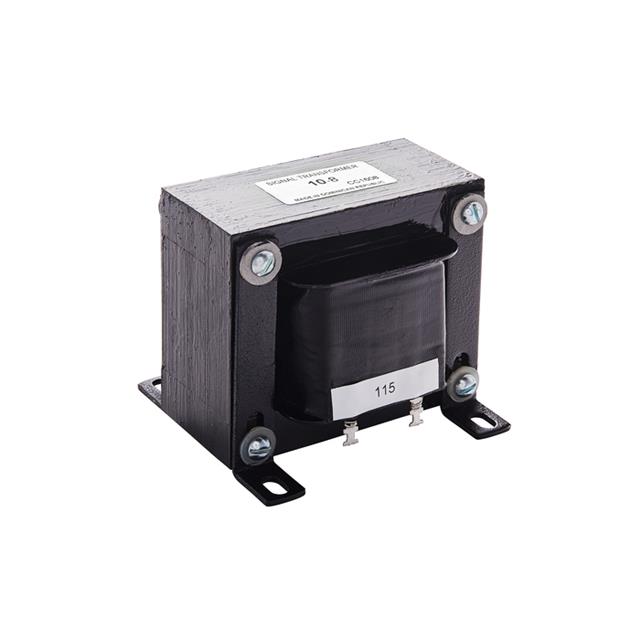
Signal Transformer 10%E6%9C%886%E6%97%A5 is used in Power Transformers category in power designs where stability, startup behavior, and thermal headroom need to be measurable. Key specs include Description (PWR XFMR LAMINATED 60VA CHAS MT), Mounting (Chassis Mount), and Packaging (Box).

Selection Notes
  • For 10%E6%9C%886%E6%97%A5, ensure the supply current (Parallel 12A, Series 6A) is acceptable for battery life and thermal limits.
  • Verify Center Tap (Yes) matches your requirements and the datasheet test conditions.
  • Make sure the mounting type (Chassis Mount) matches how the part will be installed and inspected.
  • Make sure Voltage - Secondary (Full Load) (Parallel 5V, Series 10V) aligns with your design targets and verification plan.
Alternates & Substitutions
  • For Power Transformers, treat alternates as an integration task and validate the assumptions that matter on the assembled system.
  • Confirm startup states and fault behavior are equivalent so the alternate does not change system behavior during brownouts or resets.
  • Keep the assembly and footprint constraints consistent (mounting Chassis Mount, packaging Box) to avoid a late PCB change.
  • For power parts, match input/output limits first, then validate stability, protection behavior, and thermals under load steps and transients.
FAQ

Any tips for derating and validation for 10%E6%9C%886%E6%97%A5?
Validate at worst-case temperature and load, confirm thermal headroom, and check protection and startup behavior with margin.

Which Size / Dimension is specified for 10%E6%9C%886%E6%97%A5?
85.70mm L x 69.90mm W

Which Power - Max is listed for 10%E6%9C%886%E6%97%A5?
60VA

Is 10%E6%9C%886%E6%97%A5 surface-mount or through-hole?
Chassis Mount

Application Scenarios

In the Power Transformers category, Signal Transformer 10%E6%9C%886%E6%97%A5 is often evaluated by how well it fits electrical, thermal, and mechanical constraints in the target system. A well-chosen power solution reduces nuisance resets and shortens debug cycles by keeping rails inside margin across corners. Power-stage choices tend to pay back in validation time by making EMI, thermal headroom, and protection behavior easier to prove. Within battery-powered sensors and wearables, low standby current and clean switchover behavior protect both runtime and stored data. Across automotive ECUs, they handle cranking dips and load dumps while meeting EMI requirements and protecting mixed-voltage sensor domains. In real deployments, across edge servers and communications modules, multi-rail sequencing and telemetry protect compute and memory during rapid load steps. In battery-powered tools and portable medical devices, efficiency and low quiescent current extend runtime while keeping transient behavior predictable.

Compatibility Advice
  • In practice, validate magnetic components under the real waveform so saturation and audible noise are not discovered late. This keeps qualification evidence reproducible later.
  • During bring-up and production test, verify ripple and load-step response at the point of load, because rails can look fine at the regulator but fail at the consumer. This avoids one-off tuning in production.
Project Fit
  • Works best when you can verify Signal Transformer 10%E6%9C%886%E6%97%A5 for Power Transformers integration in the final enclosure, and you need stable impedance or ESR behavior that remains predictable after heat soak. However, usually not a good fit when integrating Signal Transformer 10%E6%9C%886%E6%97%A5 for Power Transformers, derating and self-heating cannot be verified, so performance drift may appear after deployment, because integration risk stays high when key margins cannot be measured.
10月6日10月6日
$70.22
Buy Now