ChipApex | Global Electronic Components Supplier
2-1462051-5
Search Product
Search Post
— IC芯片 | 连接器 | 传感器 | 被动器件 —
Search productSearch post
— IC芯片 | 连接器 | 传感器 | 被动器件 —
Consult the customer manager about the wholesale price.
consultation hotline:86-132-6715-2157
email:chipapexlimited@gmail.com
Contact the product manager for consultation. One-stop consultation is available.
Do you want a lower wholesale price? Please send us your inquiry and we will reply immediately.
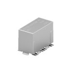
TE Connectivity Potter & Brumfield Relays 2-1462051-5 is used in High Frequency (RF) Relays category in RF signal paths where layout, grounding, and interface choices determine real performance. Key specs include Description (RELAY RF SPDT 2A 4.5V), Temperature (-55°C ~ 85°C), Mounting (Surface Mount), and Packaging (Tape & Reel (TR), Cut Tape (CT)).
Any tips for integrating 2-1462051-5 into an RF signal path?
Pay attention to impedance continuity, grounding, connector transitions, and layout symmetry to minimize loss and reflections.
What Must Operate Voltage does 2-1462051-5 have?
3.38 VDC
What current consumption is specified for 2-1462051-5?
31 mA
Can you confirm the Contact Rating (Current) for 2-1462051-5?
2:00 AM
TE Connectivity Potter & Brumfield Relays 2-1462051-5 in the High Frequency (RF) Relays category is typically selected when engineers need predictable, spec-driven behavior in a production design. Good RF building blocks accelerate certification and reduce re-spin risk in antenna-to-baseband designs. RF parts are judged by how they behave on the board: impedance environment, coupling, shielding, and the real antenna or load. This is why the following scenarios matter: they reflect the environmental and integration stresses that dominate outcomes. From an engineering workflow standpoint, this is where bench validation and field constraints meet. Within medical telemetry, controlled emissions and stable links are prioritized around sensitive instruments. In IoT gateways, matching and filtering improve sensitivity and coexistence in crowded 2.4 GHz and sub-GHz environments. Across industrial sensing, RF front ends support radar and presence detection where phase noise and filtering influence range accuracy.
 2-1462051-5
The activity of extra discounts on wholesale prices is in full swing…
Please fill in your contact information and we will send you the latest wholesale price list.