ChipApex | Global Electronic Components Supplier
74AHCT1G07QSE-7
Search Product
Search Post
— IC芯片 | 连接器 | 传感器 | 被动器件 —
Search productSearch post
— IC芯片 | 连接器 | 传感器 | 被动器件 —
Consult the customer manager about the wholesale price.
consultation hotline:86-132-6715-2157
email:chipapexlimited@gmail.com
Contact the product manager for consultation. One-stop consultation is available.
Do you want a lower wholesale price? Please send us your inquiry and we will reply immediately.
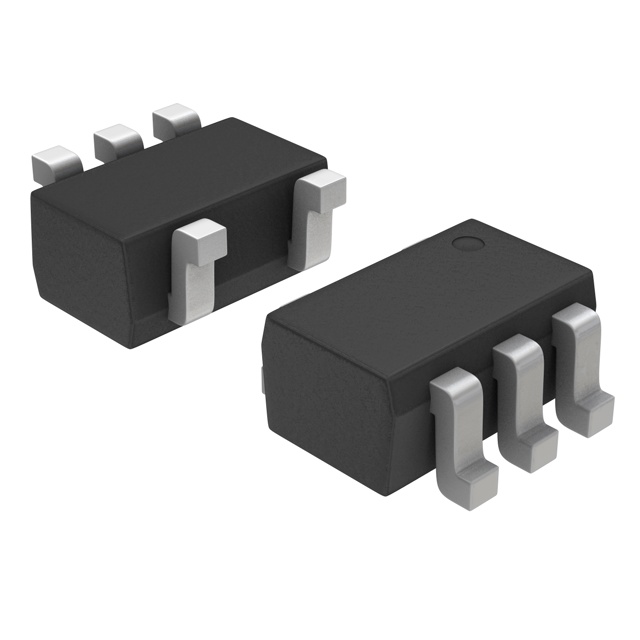
Diodes Incorporated 74AHCT1G07QSE-7 is a component in Buffers, Drivers, Receivers, Transceivers category typically evaluated for fit, operating limits, and supportability in production. Key specs include Description (IC BUFFER NON-INVERT 5.5V SOT353), Series (74AHCT), Packaging (Tape & Reel (TR), Cut Tape (CT)), Supply (4.5V ~ 5.5V), and Temperature (-40°C ~ 125°C (TA)).
What should I compare when selecting an alternate for 74AHCT1G07QSE-7?
Compare footprint/pinout, key electrical limits, temperature range, and interface requirements, then validate under worst-case conditions.
Which output type is specified for 74AHCT1G07QSE-7?
Open Drain
Which Grade is listed for 74AHCT1G07QSE-7?
Automotive
Which supply current is specified for 74AHCT1G07QSE-7?
-, 8mA
Selecting Diodes Incorporated 74AHCT1G07QSE-7 for Buffers, Drivers, Receivers, Transceivers usually comes down to meeting the system constraints that matter most: limits, interfaces, and testability in the real build. Within mixed-voltage boards, clean translation and buffering reduce contention risk and protect interfaces during hot-plug and brownout events. They implement deterministic digital interface and control functions such as buffering, decoding, timing, and level translation with predictable latency. Across consumer devices, small logic functions simplify validation for high-volume builds. In industrial networks, robust physical interfaces support long cables and noisy grounds where termination and protection strategy must be validated. Within dense boards, proper buffering reduces loading on controllers and improves timing margin across temperature and lot variation. In practice, from an engineering workflow standpoint, this is where bench validation and field constraints meet. In practice, when margins are designed in, performance tends to stay stable even when operating conditions are not ideal.
 74AHCT1G07QSE-7
The activity of extra discounts on wholesale prices is in full swing…
Please fill in your contact information and we will send you the latest wholesale price list.