TXM-900-HP3-PPO

TXM-900-HP3-PPO

$26.33
  • Description:RF TX IC FM/FSK 902-928MHZ 10SIP
  • Series:HP3
  • Mfr:TE Connectivity Linx
  • Package:Tube

SKU:aaecbb83db28 Category: Brand:

  
  • Quantity
    • -
    • +
  •    
ChipApex WhatsApp

Consult the customer manager about the wholesale price.

consultation hotline:86-132-6715-2157

email:chipapexlimited@gmail.com
Contact the product manager for consultation. One-stop consultation is available.


Do you want a lower wholesale price? Please send us your inquiry and we will reply immediately.

*
*
*
*
Submitting!
Submission successful!
Submission failed!
Email error!
Phone number error!

Product Detailed Parameters

  • Description:RF TX IC FM/FSK 902-928MHZ 10SIP
  • Series:HP3
  • Mfr:TE Connectivity Linx
  • Package:Tube
  • Frequency:902MHz ~ 928MHz
  • Applications:ISM, Remote Monitoring, Telemetry, Voice / Audio
  • Modulation or Protocol:FM, FSK
  • Data Rate (Max):56kbps
  • Power - Output:-3dBm ~ 3dBm
  • Current - Transmitting:14mA
  • Data Interface:PCB, Through Hole
  • Antenna Connector:Through Hole
  • Memory Size:-
  • Features:Multiple Channels, Analog and Digital Data
  • Voltage - Supply:2.8V ~ 13V
  • Operating Temperature:-30°C ~ 85°C
  • Mounting Type:Through Hole
  • Package / Case:10-SIP
  • Supplier Device Package:Module
  • Grade:-
  • Qualification:-

Download product information

TXM-900-HP3-PPO

Buying Guide
Summary

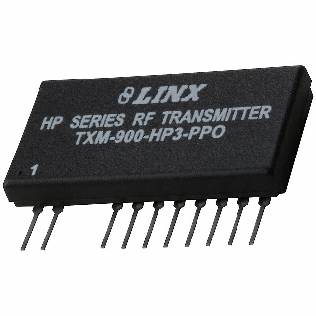
TE Connectivity Linx TXM-900-HP3-PPO is evaluated in RF Transmitters category when frequency coverage and integration details must hold up in the real enclosure. Key specs include Description (RF TX IC FM/FSK 902-928MHZ 10SIP), Temperature (-30°C ~ 85°C), Package/case (10-SIP), Mounting (Through Hole), and Packaging (Tube).

Selection Notes
  • For TXM-900-HP3-PPO, verify the operating temperature range (-30°C ~ 85°C) and derate as needed in your application.
  • Double-check Current - Transmitting (14mA) against your specification and operating conditions.
  • Double-check the mounting type (Through Hole) for your intended installation method.
  • Confirm the supply current (14mA) is acceptable for standby and active operation.
Alternates & Substitutions
  • For RF Transmitters substitutions, lock footprint/pinout and operating envelope first, then verify the critical performance conditions on your hardware.
  • Confirm the physical match (package/case 10-SIP, supplier package Module, mounting Through Hole) and the operating corners (supply 2.8V ~ 13V, temperature -30°C ~ 85°C) so the substitution is not a hidden redesign.
  • For RF parts, validate the alternate in the real enclosure and cabling, not only in a bench setup.
  • If you need a second source, provide (package 10-SIP, supply 2.8V ~ 13V, interface PCB, Through Hole, frequency 902MHz ~ 928MHz) and we will suggest options to evaluate under a clear test plan.
FAQ

What temperature range is listed for TXM-900-HP3-PPO?
-30°C ~ 85°C

What Applications is listed for TXM-900-HP3-PPO?
ISM, Remote Monitoring, Telemetry, Voice / Audio

Can you confirm the Power - Output for TXM-900-HP3-PPO?
-3dBm ~ 3dBm

What Data Interface does TXM-900-HP3-PPO have?
PCB, Through Hole

Application Scenarios

Selecting TE Connectivity Linx TXM-900-HP3-PPO for RF Transmitters usually comes down to meeting the system constraints that matter most: limits, interfaces, and testability in the real build. In practice, because RF is system-defined, teams validate with realistic antennas, cables, and enclosures rather than assuming lab fixtures represent the product. In practice, return paths and coupling decide outcomes, so designers treat placement, shielding, and grounding as first-class requirements. Within automotive connectivity, RF margins are validated against EMI from power electronics and harsh thermal cycling. In fixed wireless access, front-end linearity and filtering margins affect throughput when multiple carriers and interferers coexist. Within industrial radios, RF parts are validated for drift and detuning as enclosures heat soak and cable routing varies between installs. That combination typically reduces re-spin risk and shortens the path to compliance and production release.

Compatibility Advice
  • Before release to production, check insertion loss, group delay, and impedance behavior across temperature so link budgets stay stable. This avoids one-off tuning in production.
  • In practice, for high-speed links, validate impedance and return-path continuity end-to-end so SI margins hold beyond lab cabling across temperature and supply corners.
  • To avoid late surprises, verify coexistence and desense risks with nearby clocks and switchers so range does not collapse in the product. This keeps qualification evidence reproducible later.
Project Fit
  • Good fit when you can measure and verify TE Connectivity Linx TXM-900-HP3-PPO for RF Transmitters integration under realistic load and noise, and you can control layout, shielding, and the antenna environment.
  • Poor fit when compliance margins are tight but spurs and harmonics are not measured under real modulation, because the integration depends on constraints that cannot be controlled across builds.
TXM-900-HP3-PPOTXM-900-HP3-PPO
$26.33
Buy Now