ChipApex | Global Electronic Components Supplier
U7004B-MFSG3
Search Product
Search Post
— IC芯片 | 连接器 | 传感器 | 被动器件 —
Search productSearch post
— IC芯片 | 连接器 | 传感器 | 被动器件 —
Consult the customer manager about the wholesale price.
consultation hotline:86-132-6715-2157
email:chipapexlimited@gmail.com
Contact the product manager for consultation. One-stop consultation is available.
Do you want a lower wholesale price? Please send us your inquiry and we will reply immediately.
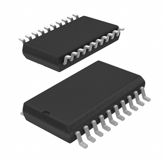
Microchip Technology U7004B-MFSG3 is used in RF Transceiver ICs category in RF signal paths where layout, grounding, and interface choices determine real performance. Key specs include Description (IC RF TXRX ISM>1GHZ 20SSO), Temperature (-25°C ~ 70°C), Package/case (20-LSSOP (0.173", 4.40mm Width)), Mounting (Surface Mount), and Packaging (Tape & Reel (TR)).
Any tips for integrating U7004B-MFSG3 into an RF signal path?
Pay attention to impedance continuity, grounding, connector transitions, and layout symmetry to minimize loss and reflections.
What is the packaging of U7004B-MFSG3?
Tape & Reel (TR)
What Current - Transmitting is listed for U7004B-MFSG3?
450mA
What operating frequency does U7004B-MFSG3 run at?
1.9GHz
Within practice, the question for Microchip Technology U7004B-MFSG3 in RF Transceiver ICs is whether it stays inside the electrical/thermal envelope while remaining easy to validate and support. Selection usually balances margin, qualification evidence, availability, and how repeatable the tuning process is in production. Teams often favor RF parts with clear reference layouts and measured example designs, because layout determines whether the numbers are reachable. In practice, within aerospace and defense, RF designs prioritize predictable link margin and controlled emissions over long lifecycles. Across security and access control, RF performance under metal proximity and long cable runs determines reliability in real buildings. In point-of-sale and retail IoT, RF reliability matters in metal-heavy environments with dense Wi‑Fi and Bluetooth traffic.
 U7004B-MFSG3
The activity of extra discounts on wholesale prices is in full swing…
Please fill in your contact information and we will send you the latest wholesale price list.