ChipApex | Global Electronic Components Supplier
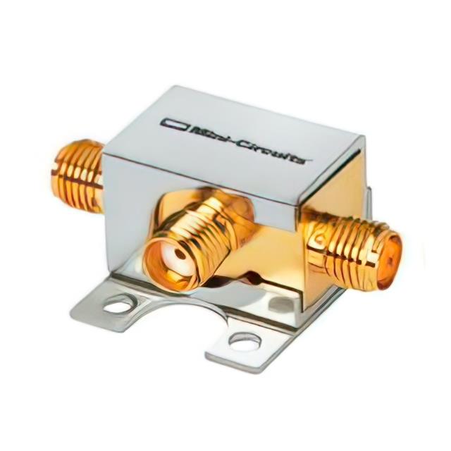
ZDPLX-2150-S+
Search Product
Search Post
— IC芯片 | 连接器 | 传感器 | 被动器件 —
Search productSearch post
— IC芯片 | 连接器 | 传感器 | 被动器件 —
Consult the customer manager about the wholesale price.
consultation hotline:86-132-6715-2157
email:chipapexlimited@gmail.com
Contact the product manager for consultation. One-stop consultation is available.
Do you want a lower wholesale price? Please send us your inquiry and we will reply immediately.
Mini-Circuits ZDPLX-2150-S is used in RF Multiplexers category in RF signal paths where layout, grounding, and interface choices determine real performance. Key specs include Description (DIPLEXER, 50-2150/DC-10 MHZ), Frequency range (0Hz ~ 10MHz / 50MHz ~ 2.15GHz), Package/case (Module), Mounting (Chassis Mount), and Packaging (Box).
Who is the manufacturer of ZDPLX-2150-S?
Mini-Circuits
Any tips for integrating ZDPLX-2150-S into an RF signal path?
Pay attention to impedance continuity, grounding, connector transitions, and layout symmetry to minimize loss and reflections.
How is ZDPLX-2150-S mounted?
Chassis Mount
Which frequency range is listed for ZDPLX-2150-S?
0Hz ~ 10MHz / 50MHz ~ 2.15GHz
For many RF Multiplexers designs, Mini-Circuits ZDPLX-2150-S is vetted against electrical margins, thermal headroom, and mechanical integration before the BOM is frozen. Selection usually balances margin, qualification evidence, availability, and how repeatable the tuning process is in production. Teams often favor RF parts with clear reference layouts and measured example designs, because layout determines whether the numbers are reachable. With interfaces and limits agreed, the next step is proving measured behavior on the real PCB and harness. Across automotive GNSS, filtering and shielding influence sensitivity under inverter and DC-DC interference. Within aerospace telemetry, predictable RF routing and isolation improve resilience to interference and maintain link margin over long distances. Across industrial sensing, RF front ends support radar and presence detection where phase noise and filtering influence range accuracy. For fielded equipment, repeatability and documentation often matter as much as peak performance, and this approach supports both.
 ZDPLX-2150-S+
The activity of extra discounts on wholesale prices is in full swing…
Please fill in your contact information and we will send you the latest wholesale price list.